Dipole antenna is one of the most fundamental and widely used antenna types in communication systems. Renowned for their simplicity and efficiency, dipole antennas play a pivotal role in enabling wireless communication across various applications, from radio broadcasting to modern IoT and 5G networks. Their versatility and ease of implementation have made them a turning point in the evolution of communication technology.
This article explores dipole antennas in depth and fundamental principles. We will examine their key characteristics, different types, and radiation patterns. Advanced configurations, such as array antennas and dual-polarized designs, will be discussed to highlight their adaptability in modern systems. Additionally, we’ll dive into the applications, advantages, and limitations of dipole antennas and compare them to monopole antennas. Finally, we’ll explore their role in modern technology, including IoT, 5G, and space communication. By the end, you will gain a clear understanding of why dipole antennas remain indispensable in communication systems.
What is a Dipole Antenna and How Does It Work?
The simplest yet widely used type of antenna in radio and telecommunications is the dipole antenna, which is made up of two conducting elements or rods that send and receive electromagnetic waves. Typically, the two conductive parts have equal lengths of metal. It is an essential component of wireless communication systems due to its simple design, which allows it to efficiently send and receive signals across a broad frequency range.
An electric field is created around the antenna when an alternating current (AC) is applied to the feedline. The electric field shifts direction in conjunction with the AC current, producing electromagnetic waves that radiate from the antenna.
The length of the dipole antenna is important for its ability to function. It needs to be a certain percentage of the radio signal wavelength that it is intended to send or receive. The term “half-wave dipole antenna” refers to the fact that this length is usually half the wavelength. The antenna effectively transforms electrical energy into radio waves when the length and wavelength are matched.
Dipole antennas broadcast and receive signals equally well in two opposed directions perpendicular to the antenna, which is known as a bidirectional radiation pattern. This is due to the fact that the AC current’s electric field is weakest at the ends of the antenna and highest in the center. Consequently, the majority of the energy emitted by the antenna is directed perpendicularly to its length.
An alternating current is created in the conductors of a dipole antenna when radio waves affect it. A receiver or other electronic equipment can be powered by this current once it has been transmitted to the feedline. By transforming the radio waves back into electrical energy, the dipole antenna serves as a receiving antenna.
Thus, when sending, a dipole antenna transforms electrical energy into radio waves, and when receiving, it transforms radio waves back into electrical energy. For effective signal transmission and reception, its length and design are important.
Key Characteristics of a Dipole Antenna
1. Simple Design
A dipole antenna’s structure, which consists of two conducting parts of equal length coupled to a feedline, makes it simple. Its simple design facilitates deployment and manufacturing. Dipole antennas can be made to work in the radio frequency spectrum’s HF (high frequency), VHF (very high frequency), and UHF (ultra-high frequency) bands.
2. Resonance at Half Wavelength
The elements of a dipole antenna typically have half the operating frequency’s wavelength. Maximum radiation efficiency is made possible by this resonance. Because the dipole’s length is half wave and the first resonant length, its radius has no effect on its input impedance. At its resonant frequency, which happens at its resonant length, an antenna operates efficiently.
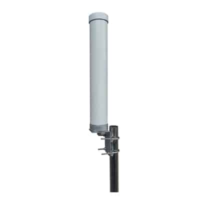
3. Omnidirectional Radiation Pattern
This omnidirectional radiation is perfect for linking devices on the same plane and on opposite sides of one another because of their doughnut-shaped emission pattern. These are frequently misused in mobile and in-building applications. Omnidirectional Dipole Antennas in mobile applications lack the proper patterning required to connect to a tower at a significantly greater elevation. Omnidirectional dipole antennas in certain applications are particularly bad in point-to-multipoint deployments, where a user may be in a dead zone while standing immediately underneath a transmitting antenna.
4. Linear Polarization
The polarization of a dipole antenna is linear by nature. The orientation of the polarization will depend on how the antenna is mounted. Energy is transmitted along a direction perpendicular to the dipole’s rod when a dipole antenna radiates broadside.
5. Gain
Antenna Gain is a specific parameter used to measure the amount of directivity of the radiation pattern of the antenna. In particular, a high-gain antenna will emit in a certain direction. Antenna gain is a passive phenomenon in which electricity is simply reallocated to provide more radiated power in a particular direction rather than being added through the antenna. The antenna’s gain can be expressed as dBi and dBd.
In relation to reference dipole antenna, dipole antenna gain can be computed in dBd. Dipole antenna gain is 2.15 dBi as a reference. Using the formula dBi = dBd + 2.15, it is quite easy to change between dBi and dBd by adding or subtracting 2.15.
Types of Dipole Antennas
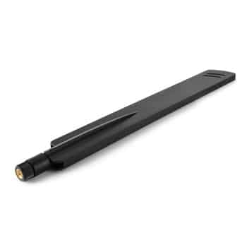
1. Half-Wave Dipole Antenna
Half-wave dipole antennas are a specific type of dipole antenna in which the dipole length is half the wavelength at the operating frequency. This antenna is also usually referred to as the Hertz antenna. Compared to other antennas, this one has a simpler resonance structure, making it suitable for both transmission and reception in a variety of applications. This antenna operates in the frequency range of 3 kHz to 300 GHz.
Half-wave dipole antennas provide the following benefits: they are lightweight, cost-effective, and have an input impedance that is comparable to that of the transmission line. A half-wave antenna’s drawbacks include its omnidirectional radiation pattern and its independence, which allows it to serve as the basic component for other kinds of antennas that operate at very high frequencies. TV and radio receivers are the primary devices that use these antennas.
2. Folded Dipole Antenna
A folded type of antenna is a group of two-dipole antennas that are simply joined one at a time to form a thin wire loop. As the name implies, the dipole antenna is folded back and consists of two half-wave dipoles, one of which is split in the center and the other continuous. At both ends, these are folded and joined in parallel.
The radiation pattern of a folded dipole antenna is comparable to that of a regular dipole, with the exception of a greater input impedance and bidirectional directivity. The wide bandwidth and high feed impedance value of this antenna are the primary characteristics of its use. As a result, these antennas are used independently, as a key part of other antennas, and to deliver high bandwidth. There are two-wire and three-wire types of these antennas.
3. Short Dipole Antenna
The most basic type of antenna is the short dipole. It is only a wire that is fed at its center and is open-circuited. In antenna engineering, the terms “small” or “short” always mean “relative to a wavelength”. Therefore, only the wire’s size in relation to the operating frequency’s wavelength matters, not the dipole antenna’s exact size. If a dipole’s length is less than a tenth of a wavelength, it is generally considered short.
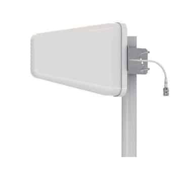
4. Log-Periodic Dipole Antenna
A directional, multi-element antenna with a broad frequency range of operation is called a log-periodic antenna. It is perfect for applications that need reliable, frequency-agile communication solutions because of its distinctive geometric structure, which enables consistent performance and gain over its bandwidth.
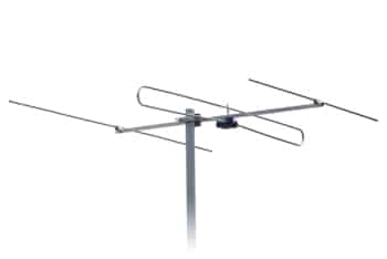
5. Crossed Dipole Antenna
A crossed dipole antenna, also known as a turnstile antenna, is a type of radio antenna made up of two identical dipole antennas that are fed in phase quadrature and positioned at right angles to one another. The two currents that are applied to the dipoles are 90 degrees out of phase. The idea that the antenna resembles a turnstile when positioned horizontally is reflected in the name.
There are two modes of operation for the antenna. The antenna emits radio waves that are horizontally polarized and perpendicular to its axis when it is in normal mode. The antenna emits circularly polarized radiation along its axis while in axial mode. For MIMO and satellite applications, these antennas are perfect.
Radiation Pattern of Dipole Antennas
The radiation pattern of a dipole antenna is toroidal, resembling a doughnut. It has maximum radiation perpendicular to the antenna axis and minimal radiation along the axis. This pattern is effective for horizontal communication, making dipole antennas highly versatile.
The main 2 advanced Dipole Configurations are:
1. Array Antennas Using Dipoles
Arrays of dipole antennas can be used to increase coverage, gain, and directivity. Large-scale communication systems and radar are two examples of applications that use these arrays. Several dipoles, often half-wave dipoles, are used in the construction of various array antenna types. Utilizing multiple dipoles is intended to boost the antenna’s directional gain above that of a single dipole, the radiation from the individual dipoles interferes with increased power emitted in specific directions. The feedline is divided using an electrical network to supply power to the elements in arrays with numerous dipole-driven elements. The relative phase delays resulting from transmission between the common point and each element are carefully considered.
In order to improve antenna gain in horizontal directions you can stack antennas in the vertical direction in a broadside array where the antennas are fed in phase with one another. This preserves the directionality of the horizontal dipole antennas and null in the direction of their elements. That null direction, however, becomes vertical in a so-called collinear antenna array if each dipole is vertically oriented. This allows the array to acquire the usually required omnidirectional radiation pattern (in the horizontal plane). In the VHF and UHF frequency bands, where the wavelengths of the elements are small to feasibly stack several on a tower, vertical collinear arrays are used.
2. Dual-Polarized Dipole Designs (MIMO Antennas)
Dual-polarized dipoles may handle multiple signals at once by using two antennas that are orthogonally polarized. Modern wireless networks benefit greatly from this design, which is essential to MIMO systems and increases data throughput and reliability. An antenna that can simultaneously receive and transmit radio frequency signals with two different polarizations, typically horizontal or vertical polarization is known as a dual-polarity MIMO antenna.
In the direction of propagation, RF signals are emitted by linearly polarized antennas in a single plane. In addition to requiring alignment between the transmitter and receiver, linearly polarized antennas can be oriented either vertically or horizontally. Antennas with circular polarization emit radio frequency in a cylindrical pattern.
Both horizontal and vertical radio frequency patterns are simultaneously emitted by dual polarized antennas. The application of dual polarity antennas in high-density settings is its main benefit over horizontal and vertical polarity antennas. Areas with a high population density experience extreme radio frequency congestion, which includes high levels of interference and noise. In contrast to traditional linearly polarized antennas, which radiate in only one linear pattern, dual polarity antennas overcome congestion by emitting in both horizontal and vertical patterns.
There are three techniques to polarize RF antennas: the most frequent is vertical polarization, followed by horizontal polarization and the least popular is circular polarization. The RF waveform’s orientation is determined by the electric field’s plane.
What is a Dipole Antenna Used For?
Dipole antennas are important in communication systems due to their adaptability. Here are some most used applications:
1. Radio Broadcasting
Radio communication devices like walkie-talkies and two-way radios frequently use dipole antennas. They are used for short-range signal transmission and reception.
2. Television Broadcasting
They ensure effective signal transmission and reception and are frequently seen in VHF and UHF television antennas. Television signals are sent from transmitting stations to residences via dipole antennas. They can also be utilized for receiving television signals in houses that do not have internet access or satellite television.
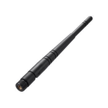
3. Wireless Communication
Dipole antennas provide reliable connectivity and are essential to Bluetooth devices, Wi-Fi systems, and other wireless networking solutions. Wi-Fi routers and access points are examples of wireless networking devices that use dipole antennas. Wireless internet access is made possible by their help in signal transmission and reception between devices.
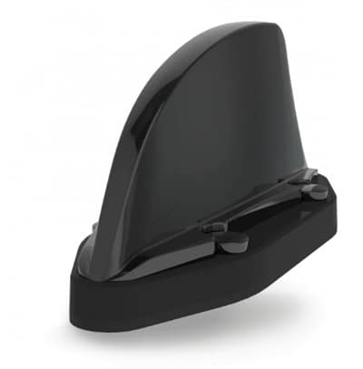
4. Cellular Networks
Base stations employ dipole antennas to provide cellular communication, enabling reliable connectivity and fast data transfer. Cellular signals are transmitted and received by mobile phones using dipole antennas. They support reliable communication between cellular towers and mobile devices.
5. Ham Radio (Amateur Radio)
Dipole antennas are used for VHF and UHF communication because of their ease of use and efficiency. Ham radio operators, commonly referred to as amateur radio operators, frequently use dipole antennas. In ham radio communications, they are employed for both signal transmission and reception.
6. Aviation Communication
Dipole antennas are used by aircraft for VHF communication systems, which ensure efficiency and safety in aviation. Radar systems that detect and track objects like ships, airplanes, and weather patterns use dipole antennas. By assisting in the transmission and reception of radar signals, they enable the measurement of an object’s distance, speed, and direction.
Advantages of Dipole Antennas
1. Simplicity
The design of dipole antennas is simple: two conductive pieces of equal length are coupled to a feedline. Because of their simplicity, they can be built with simple knowledge of technology and tools. Additionally, because troubleshooting and repairs only require minor modifications or replacements, their straightforward method makes them easy to maintain.
2. Cost-Effectiveness
Dipole antennas are made of commonly accessible and reasonably priced materials like copper and aluminum. This, along with the straightforward design that eliminates the need for complex components, guarantees that dipole antennas are among the least expensive antenna choices. They are perfect for large-scale installations like mass-market consumer electronics or radio transmission because of their affordability.
3. Versatility
Dipole antennas can be easily modified for different frequency ranges by changing the length of the conductive elements. Due to their adaptability, they can be used for a variety of purposes, including cellular networks, high-frequency Wi-Fi, and low-frequency AM radio broadcasts. Their applicability in both traditional and modern communication systems is ensured by their capacity to operate effectively over a range of frequencies.
4. Reliable Performance
Dipole antennas have been effectively utilized for many years in wireless networks, radio and television broadcasting, and aviation communication. Their effectiveness in sending and receiving messages, as well as their regular radiation patterns, are the main reasons for their reliability. They are considered as a reliable option in both critical and non-critical systems.
5. Omnidirectional Radiation
Dipole antennas radiate energy uniformly in the horizontal plane, meaning they deliver consistent signal strength in all directions perpendicular to the antenna’s axis. They are perfect for applications like Wi-Fi and broadcasting, where the coverage in multiple directions is important, because of their omnidirectional radiation pattern. Their capacity to offer consistent horizontal coverage improves connection and guarantees reliable operation in a number of environments.
Limitations of Dipole Antennas
1. Antenna Size
The wavelength of the signal that a dipole antenna is intended to use has a direct correlation with its length. The overall length of the antenna for a half-wave dipole is half the signal’s wavelength. Longer dipole elements are needed for lower-frequency transmissions because the wavelength grows as the frequency drops. For example, a half-wave dipole used in FM radio that was designed at a frequency of 100 MHz would be roughly 1.5 meters long. For applications like AM radio broadcasting that need to operate at extremely low frequencies, this size may become unfeasible.
2. Directional Limitations
Dipole antennas radiate energy equally across the antenna and usually include an omnidirectional radiation pattern in the horizontal plane. When a focused or directed beam is needed, like in point-to-point communication systems, this becomes a limitation, even though it is beneficial for applications requiring wide coverage. Other parts, like reflectors or directors (used in Yagi-Uda antennas) or combining dipoles into arrays, are required to achieve directional radiation, which complicates the design.
3. Impedance Matching
The antenna’s impedance must match that of the transmission line and any connected devices for optimum results; in most communication systems, this is 50 or 75 ohms. In free space, the input impedance of a standard dipole antenna is around 73 ohms. Even though these are quite close to standard values, differences based on by the environment or installation setups may result in impedance mismatches, that might lead to power loss and signal reflection. Deployment becomes more complex when suitable modifications, like the use of baluns or matching circuits, are required to guarantee effective power transfer.
Dipole Antennas vs. Monopole Antennas
There are various ways in which a dipole antenna differs from a monopole antenna. Let’s analyze these two antenna types primary differences in more detail.
1. The Dipole Antenna has radiation at the bottom and fields on both sides. Conversely, monopole antenna has zero radiation below the ground plane and just one field in the top half of the area.
2. To create a synthetic ground plane, dipole antennas typically require an additional radiator. On the other hand, a monopole antenna requires a real ground plane.
3. The radiator elements of the Dipole Antenna are 180 degrees out of phase. The monopole antenna, on the other hand, has the outer conductor of a coaxial cable and the reference plane of the transmission line connection. When using a monopole antenna, these patterns make up the ground plane.
4. The radiation pattern of a dipole antenna is vertically symmetric, but that of a monopole antenna is not. While the monopole antenna’s radiation pattern depends on the ground plane’s orientation, the dipole antenna is a highly frequent type of antenna.
5. A monopole antenna has a limited number of sorts and varieties on the market, while a dipole is a common antenna with many varieties.
Dipole Antennas with Modern Technology
Dipole antennas have become crucial for 5G networks and Internet of Things devices because they offer reliable service and fast connectivity in small designs. They meet the many requirements and high data demands of modern technologies. Dipole antennas are widely employed in many wireless technology applications for wireless communication. Dipole antennas may support multi-frequency communications like 5G, LTE, Wi-Fi, etc. because they often have a large bandwidth.
In satellite communication, crossed dipole antennas are utilized for circular polarization, which allows for reliable signal transmission in space. Simple wire antennas called dipoles are frequently found in communication and satellite broadcasting systems.
Conclusion
The simplicity, affordability, and performance of a dipole antenna make it an excellent choice. It is simple to build and doesn’t need any complex tuning or matching circuitry. It can function well across a variety of frequencies and has a large bandwidth. A dipole antenna also provides a balanced feed, which reduces interference and common mode noise. All things considered, a dipole antenna is an ideal choice for multiple applications.
In conclusion, wireless communication requires dipole antennas. They provide a good balance of performance and simplicity. Understanding dipole antennas will benefit you in the wireless industry, regardless of your background.